Features
4 Channel 1×2 Optical Switch FW-OSS-1X2-4-MM-1U

Introduction
The rack-mounted optical switch serves as a crucial optical path control device, enabling manual, short-range, or remote control of optical path switching through buttons, serial port communication, and Ethernet communication. It plays a pivotal role in various optical communication applications including multi-channel optical monitoring in optical transmission systems, LAN multi-light source/detector automatic switching, and dynamic monitoring of multiple points in an optical sensor system. Additionally, it is essential for conducting tests on optical fiber, devices, networks and field engineering cable testing as well as for the installation and adjustment of optical devices.
Specifications
|
Parameters |
Indicators |
|
Channel No |
FW-OSS-1X2-4-MM-1U |
|
Wavelength Range |
850 |
|
Insertion Loss |
≤ 1.2 dB |
|
Repeatability |
≤ 0.02 dB |
|
Return Loss |
≥ 30 dB |
|
Crosstalk |
≥ 35 dB |
|
Wavelength dependent loss |
≤ 0.25 dB |
|
Polarization related loss |
≤ 0.05 dB |
|
Fiber Type |
OM3,50/125um |
|
Connector |
FC/APC |
|
Monitoring Port |
RJ45、RS-232 |
|
Working Power Supply |
AC:100~240V |
|
Working Temperature |
-10 ~ +60℃ |
|
Operating Temperature |
-40 ℃ ~ +85 ℃ |
|
Size |
19 inch standard 1U rack (483 X 230 X 45) |
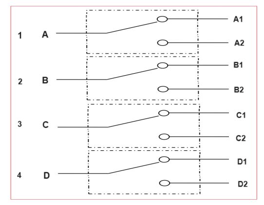
Optical path diagram

Instructions
1.Panel shows
Front panel

(1) RJ45: Ethernet 10/100M communication interface.
(2) RS-232: RS-232 communication interface.
(3) LCD display: device address, current channel and related information display.
(4) ▲ - Move up key; ▼ - Move down key; Enter - OK key; Esc - Cancel the key.
(5) A, B, C, D, A1, A2 to D1 to D2: Input and output terminals of the optical fiber (bidirectional).
(6) Power: device on, off button.
Rear panel

(1)AC power supply interface
Default Setting
Note: Users have special requirements except.
2. Description of communication port connections
(1) RS-232 interface The RS-232 interface of the device uses the DB9 female head, pin 2 is TXD, pin 3 is RXD, and pin 5 is GND.
(2), RJ45 Ethernet interface (10/100M) When the device and the computer are connected through the switch and the device is directly connected to the computer, the through line should be used (the wiring sequence at both ends is: 1-orange white, 2-orange, 3-green white, 4-blue, 5-blue white, 6-green, 7-brown white, 8-brown);
Want to know about this product?
If you are interested in our products and want to know more details,please leave a message here,we will reply you as soon as we can.